Home

Navy Labe final lr filter bode plot papetărie Redundant Opac

Bode Diagrams - Electronics-Lab.com

Low-Pass Filter
Low-Pass Filter

Filters - Low Pass and High Pass | CE Distribution

Bode diagram of the low-pass filter at the inverter output. The diagram...  | Download Scientific Diagram
Bode diagram of the low-pass filter at the inverter output. The diagram... | Download Scientific Diagram

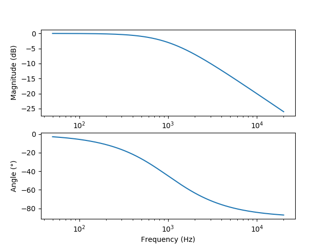
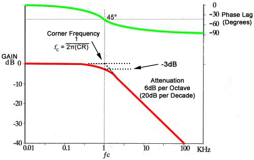
Passive Low Pass Filter - Passive RC Filter Tutorial

The bode waveform of LC filter and LCR filter. | Download Scientific Diagram

Filters - Low Pass and High Pass | CE Distribution

VSI LC filter optimized by a genetic algorithm from connected to island  microgrid operation | Energy Systems
VSI LC filter optimized by a genetic algorithm from connected to island microgrid operation | Energy Systems

Open loop Bode plot of grid current loop for LCL and LLCL filters |  Download Scientific Diagram
Open loop Bode plot of grid current loop for LCL and LLCL filters | Download Scientific Diagram

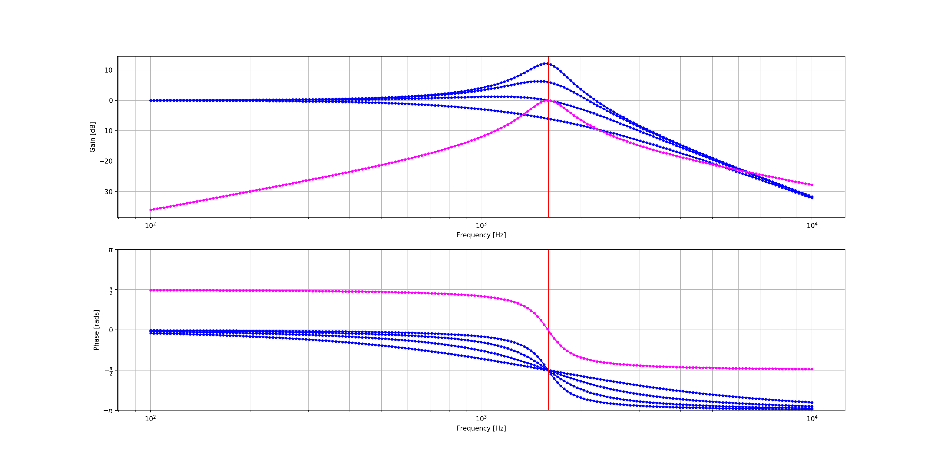
8.6.2. RLC Filter — PySpice @VERSION@ documentation

Filter Bode-plot at different loads. | Download Scientific Diagram

Filter Circuits: Frequency Response, Bode Plots, and Fourier Transform |  SpringerLink
Filter Circuits: Frequency Response, Bode Plots, and Fourier Transform | SpringerLink

Fil:Butterworth filter bode plot.png – Wikipedia

Bode plots high and low pass filter - YouTube

BODE PLOTS FIRST <wm Fll.,TERS (RC or I.R) 20 -40

Bandpass Filter Bode Plot and Analysis

Bode Plots
Bode Plots

Bode Plots for Second-Order Butterworth Filters

circuit analysis - LC low pass filter: intuitive understanding - Electrical  Engineering Stack Exchange
circuit analysis - LC low pass filter: intuitive understanding - Electrical Engineering Stack Exchange
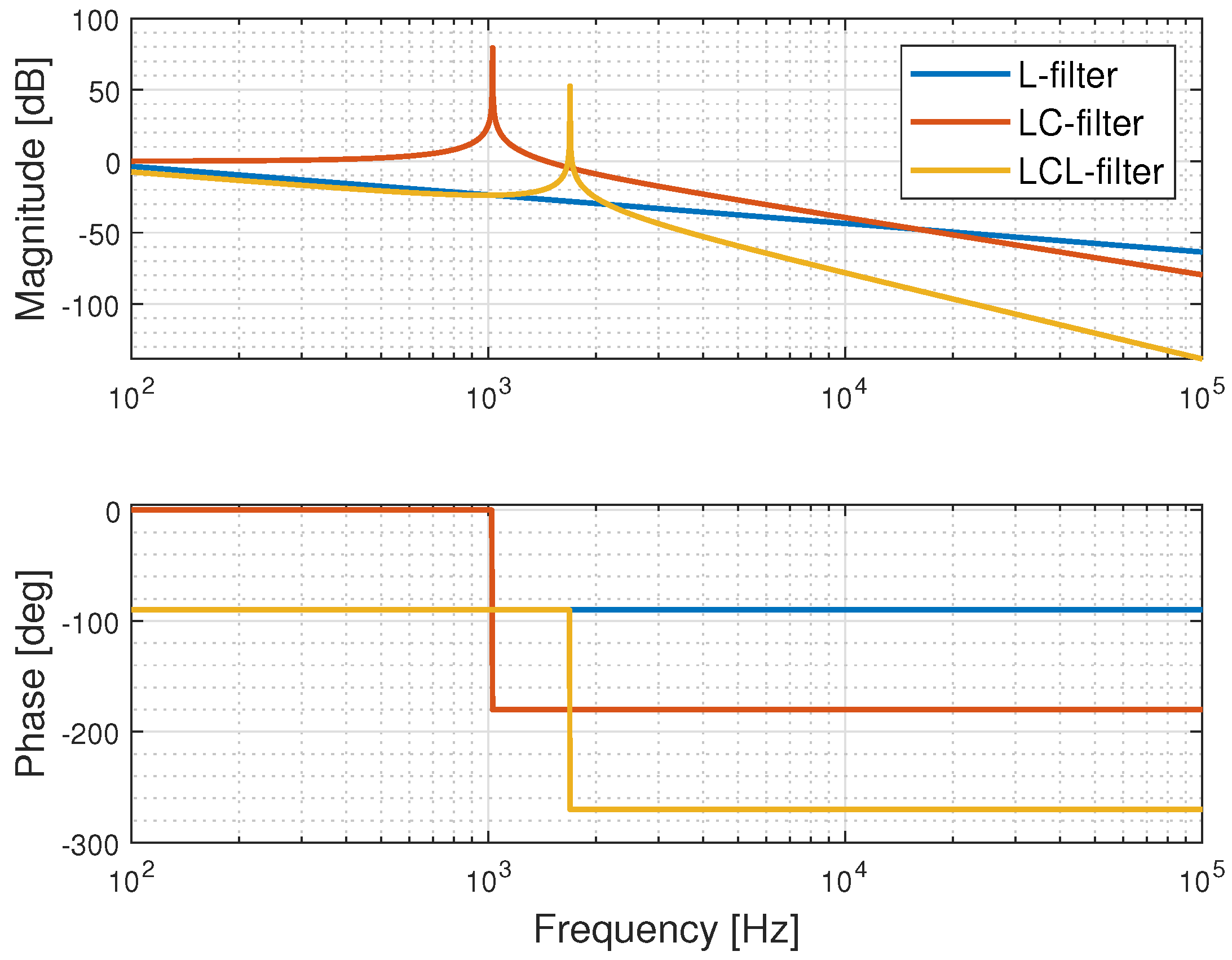
Bode diagram of LC-filter. | Download Scientific Diagram

Bode Diagram of the Second Order IIR Butterworth Band Pass Filter |  Download Scientific Diagram
Bode Diagram of the Second Order IIR Butterworth Band Pass Filter | Download Scientific Diagram

Energies | Free Full-Text | Experimental Investigation of the Frequency  Response of an LC-Filter and Power Transformer for Grid Connection
Energies | Free Full-Text | Experimental Investigation of the Frequency Response of an LC-Filter and Power Transformer for Grid Connection

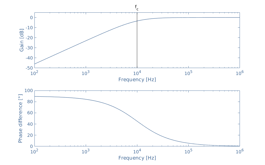
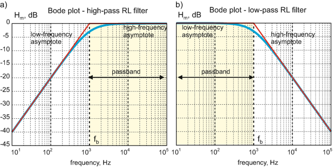
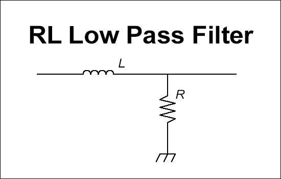
RL Low Pass Filter Calculator

Bode Plots for Second-Order Lowpass Filters with Corner Resonance

Figure 3 from Design of LCL filters for the back-to-back converter in a  Doubly Fed Induction Generator | Semantic Scholar
Figure 3 from Design of LCL filters for the back-to-back converter in a Doubly Fed Induction Generator | Semantic Scholar